For example, in the Make Reservation Use Case, in order for a Customer to request a reservation, two objects are necessary: Customer and Reception. In order for the step Check Diary for Room Availability to occur, the objects Room and Diary must exist. In order for the step Customer accepts accommodation to occur, the objects Customer and Room must exist, and so on. Looking at the steps of Make Reservation, you highlight possible objects in bold, possible class attributes in bold underline, and possible methods in italic.
|
1
|
|
2
|
|
3
|
|
4
|
Room is Available
|
|
5
|
|
6
|
Customer Requests Reservation
|
|
7
|
Provisionally Book Room
|
|
8
|
|
9
|
|
10
|
Provisionally Book Room
|
|
11
|
|
12
|
Customer Credit Is OK
|
|
13
|
Reserve Room
|
This will create a hypertext link between the two diagrams. For this tutorial, your Use Cases were in the Business Use Case View package. Build the Sequence diagrams in a Reservation System package in the Logical View package.
|
1
|
Open the Tutorial encyclopedia. (Select File > Open Encyclopedia > Existing. Select your Connection name, then highlight the Tutorial encyclopedia, click OK.)
|
|
2
|
In the UML tab of the Explorer, expand the Logical View package and right click Reservation System > New. The Select New Type for UML dialog opens.
|
|
3
|
|
4
|
Type Make Reservation in the New Diagram dialog. Click OK on the Diagram - Sequence - Make Reservations dialog to keep the default settings.
|
|
1
|
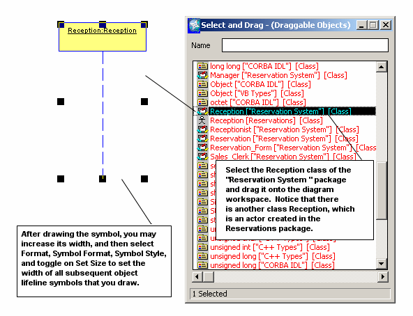
Right-click the Sequence diagram workspace, and select Choices. You can view a list of classes and objects already established in this encyclopedia.
|
|
2
|
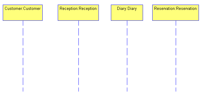
Select the Reception ["Reservation System"] [Class] and drag and drop it onto the diagram workspace. Note that there are two Reception classes–the Reception actor of the Reservations package that you created earlier, and a Reception class of the Reservations System package. Make sure that you drag this latter one onto the diagram workspace. An object Reception, instantiating the class Reception, is created. Close the Select and drag dialog.
|
|
3
|
Note By default, the Sequence diagram employs an invisible, horizontal grid that you draw and move symbols on. You can change the flexibility of this grid, or turn it off by selecting Format > Diagram Format > Grid > Reduced View. If you want to see the grid on the diagram workspace, select Format > Diagram Format > Display Options > Show grid.
|
4
|
Right-click the diagram workspace and select Choices. From the Select and drag dialog, drag and drop Diary ["Reservation System"] and Reservation ["Reservation System"] onto the diagram. Close the Select and drag dialog. Position the two objects in parallel to the other object lifelines.
|
|
1
|
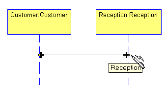
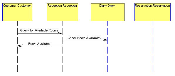
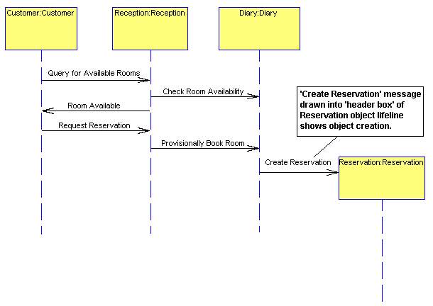
Select the Message/Stimulus tool from the toolbox and draw a message/stimulus line, starting at the object Customer and ending at the Reception object. When attaching the Event line to an object lifeline, make sure that you see a + mark on the intersection. This tells you that the lines are connected. Name the line Query for Available Rooms and press Enter. Reception responds to the event Query for Available Rooms by performing an action: It must check the Diary for room availability.
|
|
2
|
Draw a message line from the Reception object to the Diary object. Name it Check Room Availability. You will not model the return message from Diary back to Reception– leave it implied.
|
|
3
|
|
4
|
|
5
|
|
1
|
Select the Reservation object and move it down on the diagram so that the next line drawn can be drawn into its 'header box'.
|
|
2
|
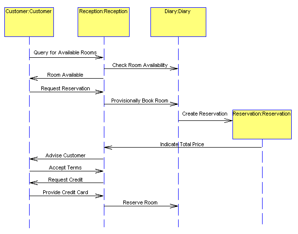
The Reservation object compute its price and notify Reception, which will advise the Customer (Diary is not involved in this pricing process). If the Customer accepts the terms, Reception is notified, which reserves the room in the diary. Diary updates the Reservation status to Reserved.
|
1
|
|
2
|
|
3
|
|
4
|
|
5
|
|
6
|
|
1
|
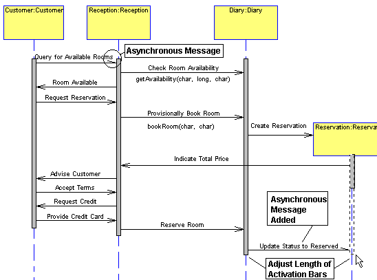
Select the Focus of Control tool on the toolbox, and drop one onto the Customer object lifeline. Notice that you can only drop a Focus of Control bar onto an object lifeline symbol. System Architect does not allow you to drop it onto empty diagram workspace.
|
|
2
|
Choose the Select Mode pointer from the toolbox (or press your Esc key) to get back your pointer. Select the Focus of Control bar, and drag on its bottom and top handlebars so that it covers the object lifeline at all points where it sends or receives a message.
|
Model the following: when Reception sends the message Check Room Availability to the object Diary, the method getAvailability is invoked. To reserve the accommodation, you need a start date, the duration of the stay, and the room type. These will be parameters of the method:
|
1
|
Open the definition of the message line Check Room Availability that is sent from the object Reception to the object Diary. (To open the definition, double-click the line or right click it and select Edit.)
|
|
2
|
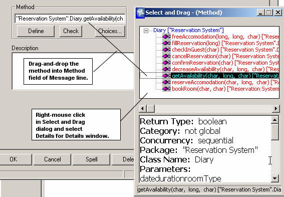
In the definition dialog, select Choices for the Methods property. The Select and Drag dialog box opens, providing you with a list of all methods of the target class, Diary. Notice these are only methods for the class Diary (the System Architect notation is to put the method name (with parameters in parenthesis), a period, and the class name.
|
|
3
|
Drag getAvailability(Date, Duration, roomType).Diary into the Methods field. Close the Select and Drag dialog.
|
|
4
|
Once you drag the method into the Operations field, you can click Define to view the full method definition.
|
|
5
|
Click OK to close the Message line definition dialog. You notice that the name of the method has been added to the diagram, under the Message line.
|
|
6
|
Turn off the display of the method name–right-click the line and select Display Mode to open the Display Mode dialog. Toggle off Method and click OK.
|
Next, add the method invoked by the message Provisionally Book Room that is sent from Reception to Diary.
First add this method to the Diary class:
|
1
|
Open the definition of the Diary object lifeline (right click and select Edit or double-click the symbol).
|
|
2
|
In the Definition tab of the definition dialog, click Define next to Class - (Class) Diary to open the definition of the class.
|
|
3
|
In the class Diary's definition dialog, click the Methods tab. You notice there are already a number of operations defined for Diary, but no method to book a room. You will add a new method.
|
|
4
|
|
5
|
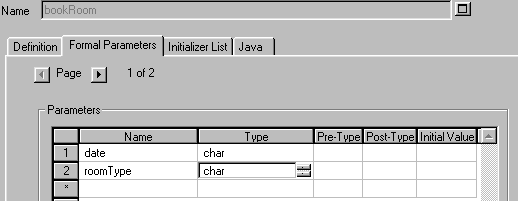
In the method's definition, select the Formal Parameters tab. In the Parameters grid, type in date and press Enter. In the Type cell, press your 'c' key to select char.
|
|
6
|
Type in a second parameter, roomType, and specify the type as char. Click OK to close the method definition dialog, and OK again to close the class definition dialog.
|
|
7
|
Open the definition of the message line Provisionally Book Room that is sent from the object Reception to the object Diary.
|
|
8
|
Click Choices for the Methods property. The Select and Drag dialog box opens, providing you with a list of all methods of the target class, Diary.
|
|
9
|
Drag bookRoom(date, roomType)."Reservation System".Diary into the Methods box. Close the Select and Drag dialog and click OK.
|
