SV-10c System Functions Event Trace (DM2) and Systems Event Trace (DM2)
The SV-10c System Functions Event Trace (DM2) diagram is one of three models used to describe system functionality. It identifies system-specific refinements of critical sequences of events described in the Operational Viewpoint.
There are two types of diagrams:
SV-10c System Functions Event Trace (DM2)
This diagram has a Service view equivalent, named SvcV-10c Service Functions Event Trace (DM2).
SV-10c Systems Event Trace (DM2)
This diagram has a Service view equivalent, named SvcV-10c Services Event Trace (DM2).
Procedure
1 Click File > New Diagram.
2 In the Select All Methods dialog, select SV-10c System Function Event Trace (DM2) or SV-10c Systems Event Trace DM2.
3 Type the name of the diagram, and then click OK.
4 In the new diagram, set the diagram properties and add symbols as needed.
You can specify the following diagram properties:
▪Description: A description of the diagram.
▪Peers: The SV-10c diagrams that are peers of the current diagram. On the SV-10c System Function Event Trace (DM2), the peers can be other SV-10c System Function Event Trace (DM2) diagrams. On the SV-10c Systems Event Trace diagram (DM2) the peers are other SV-10c Systems Event Trace diagrams (DM2).
▪Architecture Type: The types can be As Is, To Be, or Transitional.
▪Related Architectural Description: This description is the related ArchitecturalDescription definition (from the AV-01 diagram).
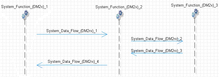
You can add the following symbols to the SV-10c System Function Event Trace (DM2) diagrams:
▪System Function: A function that is performed by a system. This is commonly refers to the automation of activities, data transformation or information exchanges in IT systems. However, it also refers to the delivery of military capabilities.
▪System Data Flow: The Data that is passed between System Functions.
Note The diagram auto-generates the System Data Flows between System Functions based on the SV-04b. Adding or deleting lines on this diagram affects the SV-04b. You can hide relationships lines by right clicking in the diagram white space and selecting Hide/Show System Data Flow (DM2rx) Relationship Lines. The hidden lines reappear each time you open the diagram.
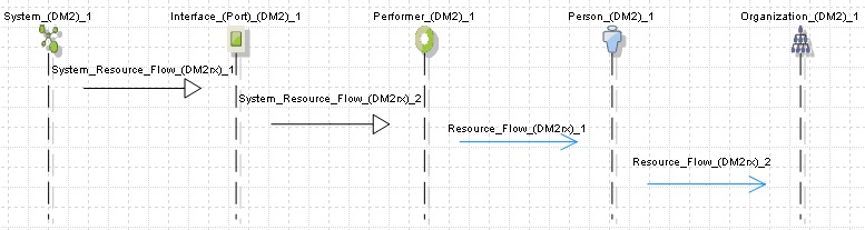
You can add the following symbols to the SV-10c Systems Event Trace diagrams:
▪System: A functionally, physically, and (or) behaviorally related group of regularly interacting or interdependent elements.
▪Interface: Interfaces in and between equipment, subsystems, systems, an SoS, or other technology driven aspects of an enterprise
▪Performer: Things that do the activities, such as service performers, systems, personnel, and organizations.
▪Organization: A specific real-world assemblage of people and other resources organized for an ongoing purpose.
▪Person: A type of performer, usually acting in a Role
▪System Resource Flow: Elements being exchanged between systems and the attributes of that exchange; a simplified representation of a pathway or network pattern
▪Resource Flow: The interaction between Activities (done by Performers) and Performers. It temporal and it results in the flow or exchange of objects such as information, data, materiel, and Performers.
Note The diagram auto-generates the System Resource Flows and Resource Flows based on the SV-01 and SV-02. Adding or deleting lines on this diagram impacts the SV-01 and SV-02. You can hide relationships lines by right clicking in the diagram white space and selecting Hide/Show Relationship Lines.