You can create capability taxonomy (hierarchy) diagram to establish capabilities that your architecture provides, or must provide. This diagram enables you to think hierarchically; you can arrange capabilities to show their composition in a tree-like structure.
This diagram is provided to the DoDAF user as an optional diagram to work with. It is the same as the StV-2 diagram from MODAF, but the diagram does not have a prefix for the DoDAF user because it is not contained in the DoDAF 1.5 specification.
1 Select File, New Diagram or select Diagrams in the All Methods tab in the explorer, right-click it, and then select New. The Select new type for All Methods dialog appears.
2 Double‑click Capability Taxonomy. The New Diagram dialog opens.
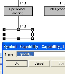
3 Enter a name and click OK. The diagram is created.
You can manually draw a Capability Taxonomy diagram. When you do so, you connect Capabilities underneath one another using System Architect's autoconnect drawing feature that is available on hierarchical-type diagrams.
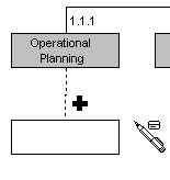
4 Select a Capability symbol from the toolbar and draw it on the diagram.
5 While still in draw mode, draw another capability symbol, and position it underneath the first Capability symbol. Keep the mouse button pressed until you see a vertical line appear between the two symbols, denoting they will be connected. Release the mouse button.
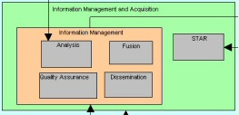
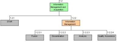
Note You can also create a capability taxonomy diagram automatically from a capability cluster diagram. With the capability cluster diagram open and in focus, save the most recent changes that you have made to the diagram; then click Tools > DoDAF Utilities > Convert StV-2 to StV-4. The new diagram is created. Capability symbols that are drawn in other capability symbols on the capability cluster diagram, denoting containment, are represented as a hierarchy on the capability taxonomy diagram.
Note The following images show a capability cluster diagram on the left and the generated capability taxonomy diagram on the right.