Modeling services on SV-2 Systems Communication diagrams
You can model services on the SV-2 diagram. You can visually specify the systems that perform the services by drawing the services in system entity symbols on the diagram. You can also show how services relate to one another by drawing a service interface line between the services.
Prerequisite
You must open an SV-2 diagram that contains system entities that you modeled previously.
The SV-2 diagram depicts specific communications links or communications networks between systems or system nodes. While SV-1 depicts interfaces between systems or systems nodes, SV-2 contains a detailed description of how each SV-1 interface is implemented by physical media, for example, communications networks, routers, and gateways.
Procedure
1 On the SV-2 diagram, in system entity symbols, draw services.
2 To show how two services relate to each other, draw service interface lines between the services.
3 Save the diagram.
Result
When you save the SV-2 diagram, the software detects the presence of service interface lines between services and updates the Client Services and Supplier Services properties of each service definition. The “to” end of the line denotes the client; for example, drawing a service interface line from Service A to Service B makes Service A the supplier service, and Service B the client service. These relationships are also represented in the SV-3 Services-to-Services matrix.
Example
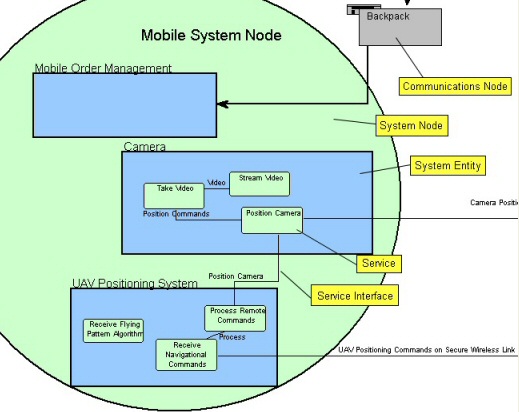
The following image shows an example of an SV-2 diagram containing a system node, Mobile System Node, which contains several system entities with services.