Modeling capabilities for the operational architecture (ABM for DoDAF)
You can capture the operational architecture when you model a capability.
Defining capabilities and capability relationships (ABM for DoDAF)
You can use capability cluster diagrams to map out capabilities and show their dependencies to one another using a capability dependency line. You may also show decomposition of capabilities, developing a capability hierarchy, by drawing capabilities within their owning capability.
This diagram is provided to the DoDAF user as an optional diagram to work with. It is the same as the StV-4 diagram of MODAF, but since the DoDAF specification does not call for it, it does not have any prefix for the DoDAF user. It is simply called the capability cluster diagram.
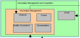
Pictured below is an example capability cluster diagrams. All rectangular symbols on the diagram, both big and small, represent capabilities. The lines drawn between capabilities are capability dependency lines. Some capabilities are shown drawn within other capabilities - this denotes composition of capabilities.
Automatically creating capability cluster diagrams from a capability taxonomy diagram (ABM for DoDAF)
You can automatically create a capability cluster diagram from a capability taxonomy diagram.
1 With the capability Taxonomy diagram open and in focus, save the most recent changes that you have made to the diagram by selecting File, Save Diagram.
2 Select Tools, DoDAF Utilities, Convert StV-2 to StV-4. The capability Cluster diagram will be automatically created. capability symbols that are drawn beneath other capability symbols - denoting containment - will be drawn within their parent capability symbol on the capability Cluster diagram.
Result
=
Establishing relationships between capabilities (ABM for DoDAF)
You use the capability dependency line to show how one capability is a supplier to another capability (the client).
1 Select the capability dependency line from the toolbar, and draw a capability dependency line from one capability to another.
2 Save the diagram.
3 In the StV-4 tab of the capability definition, you will see a list of Supplier capabilities and Client capabilities, based on the dependency lines drawn on the diagram.
Establishing hierarchies of capabilities in a capability cluster diagram (ABM for DoDAF)
You can draw capabilities within other capabilities. In so doing, you establish a composition relationship between the capability that encompasses the capability enclosed within it. The nesting is captured in the capability definition, as Parent and Child capabilities, as soon as you save the diagram. If you have built a capability taxonomy diagram, you can automatically generate a capability cluster diagram.
1 Draw two capabilities on a capability cluster diagram.
2 Drag on the handlebars of the capability you want to make the container, to make it larger.
3 Move the capability you want to have contained in the other capability, inside its enlarged symbol.
4 Save the diagram.
5 In the StV-2 tab of the capability definition, you will see a list of Parent capabilities and Child capabilities, which are filled in based on the containment of the symbols on the diagram.
In the diagram pictured below, for example, the definition of the Dissemination capability shows that it is a child of (contained within) the capabilities Information Management and Plan Engagement.
Creating capability taxonomy diagrams (ABM for DoDAF)
You can create capability taxonomy (hierarchy) diagram to establish capabilities that your architecture provides, or must provide. This diagram enables you to think hierarchically; you can arrange capabilities to show their composition in a tree-like structure.
This diagram is provided to the DoDAF user as an optional diagram to work with. It is the same as the StV-2 diagram from MODAF, but since the DoDAF specification does not call for it, it does not have a prefix for the DoDAF user, and it is simply called the capability taxonomy diagram.
1 Select File, New Diagram or select Diagrams in the All Methods tab within the explorer, right-click it, and select New. The Select new type for All Methods dialog appears.
2 Scroll down and double‑click Capability Taxonomy. The New Diagram dialog opens.
3 Enter a name and click OK. The diagram is created.
You can manually draw a Capability Taxonomy diagram. When you do so, you connect Capabilities underneath one another using System Architect's autoconnect drawing feature that is available on hierarchical-type diagrams.
4 Select a Capability symbol from the toolbar and draw it on the diagram.
5 While still in draw mode, draw another capability symbol, and position it underneath the first Capability symbol, while keeping the left mouse button down, until you see a vertical line appear between the two symbols, denoting they will be connected. Release the mouse button.
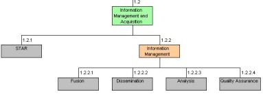
Note You can also create a capability taxonomy diagram automatically from a capability cluster diagram. With the capability cluster diagram open and in focus, save the most recent changes that you have made to the diagram; then click Tools > DoDAF Utilities > Convert StV-2 to StV-4. The new diagram is created. Capability symbols that are drawn within other capability symbols on the capability cluster diagram, denoting containment, are represented as a hierarchy on the capability taxonomy diagram.
The following images show a capability cluster diagram on the left and the generated capability taxonomy diagram on the right.
=
Viewing and specifying dependencies between capabilities (ABM for DoDAF)
This Capability-to-Capability matrix enables you to show dependencies between Capabilities. This matrix is provided to the DoDAF user as an optional matrix to work with. It is the same as the StV-4 matrix of MODAF, but since the DoDAF specification does not call for it, the matrix does not have a prefix. It is simply called the Capability Dependency matrix.
Specifying the operational activities needed to produce capabilities (ABM for DoDAF)
You can specify the operational activities needed to produce capabilities by opening the capability to operational mapping matrix. When doing so, you specify how important the operational activity is in realizing the capability: critical, important, necessary, nonessential, or low.
When you reload this matrix, analytic colors are applied to the status levels. This matrix is provided to the DoDAF user as an optional matrix to work with. It is also in the MODAF version of System Architect.
To generate the Capability to Operational Mapping matrix
1 Select View > Matrix Browser.
2 In the Matrix Browser dialog, select the Capability to Operational Mapping matrix.
3 Walk through the matrix opening wizard, that enables you to filter the contents of the matrix that is presented, click Next, and then click Finish.
The matrix opens. The following matrices also open:
▪SV-5 System Function to Operational Activity matrix
▪System Function to Operational Activity matrix
▪System to Capability matrix
▪System to System Function matrix
4 Specify each Operational Activity that provides a Capability by selecting a status from the drop-down list of the cell intersecting the two definitions. When doing so, you specify how important the Operational Activity is in realizing the Capability - Critical, Important, Necessary, Non-Essential, or Low.
5 Click Matrix > Reload to reload the matrix. Analytic colors are applied to the status levels.
6 Right-click a cell that has a status specified, and click Edit Cell Definition from the pop-up menu.
7 Notice that the cell is defined by a Capability/Operation definition. This cell definition holds the row (Capability) and column (Operational Activity) definitions, as well as other properties of the intersection, such as Status.
If you view the saprops metamodel language that enables the color analytics in this matrix, you will see the code listed below. The depictions clause is being used to fill the matrix with a color specified by the three-number code. For example, the color red (236,062,064) is used to denote a Critical status.
LIST "Capability Status Colors" { VALUE " " VALUE "1-Critical" depictions {fill color {236,062,064}} VALUE "2-Important" depictions {fill color {255,194,035}} VALUE "3-Necessary" depictions {fill color {250,219,000}} VALUE "4-Nonessential" depictions {fill color {052,126,199}} VALUE "5-Low" depictions {fill color {001,164,109}} }
You can add an entry, or change the name or color of an existing entry by adding this block of code to the usrprops for an encyclopedia, and making necessary additions or changes. See the Extensibility section of the help for details on how to edit and deploy usrprops.
Generating reports that relate capabilities, operational activities, and nodes (ABM for DoDAF)
You can run reports that show each capability, which operational activities are performed to provide it, and which operational nodes those activities are performed on.
From the capability-to-operational activity association, you can infer which operational nodes are related to capabilities. However, an operational activity can be provided on many operational nodes. You can run reports that show each capability, which operational activities are performed to provide it, and which operational nodes those activities are performed on.
Modeling net-centric architectures (ABM for DoDAF)
Starting with DoDAF 1.5, users are encouraged to build net-centric architectures, and establish capabilities and services provided and used by the architecture. Within an operational node definition, you can specify if the node is a service provider, service consumer, or unanticipated user of services.
These three operational node definitions are prepopulated into every encyclopedia. You might create new operational node instances; however the DoDAF specification specifically calls out to categorize nodes by one or more of these three roles.
1 In the diagram, double-click an operational node.
2 In the operational node definition dialog box, specify if the node is a Service Provider, Service Consumer, or Unanticipated User of Services.