Modeling services on SV-2 systems communication diagrams (ABM for DoDAF)
You can model services on the SV-2 diagram. You can visually specify the systems that perform the services by drawing the services within system entity symbols on the diagram. You can also show how services relate to one another by drawing a service interface line between the services.
Prerequisite
You must open an SV-2 diagram that contains system entities that you modeled previously.
The Systems Communication Diagram provides more detail to the system interfaces that are seen on the SV-1 Systems Interface Diagram. Note that this diagram adds to the single- line representation of the interfaces shown on the SV-1 diagram detail about the communication infrastructure. Depending on the focus of the architecture the diagram can present the modeler with an internodal or intranodal perspective. The internodal approach details the communication paths and/or networks that internally connect system nodes or specific systems. The intranodal approach looks within the system nodes to pinpoint the interfaces between specific containing nodes.
You can model the following symbols on the Systems Communication diagram:
▪System Node Interface: Allows data to be passed only between system node symbols
▪System Node: Describes the operation or role and allocation of resources to perform a particular role/operation
▪System Interface: Allows data information to be exchanged only between System Entities
▪System Entity: Describes the system functions that need to be preformed
▪Communications Node: Controls the transfer and movement of information
▪Communications Connection: The connection can describe the nature of the communication path, for example the kind of channel or network
Procedure
1 On the SV-2 diagram, within system entity symbols, draw services.
2 To show how two services relate to each other, draw service interface lines between the services.
3 Save the diagram.
Result
When you save the SV-2 diagram, the software detects the presence of service interface lines between services and updates the Client Services and Supplier Services properties of each service definition. The “to” end of the line denotes the client; for example, drawing a service interface line from Service A to Service B makes Service A the supplier service, and Service B the client service. These relationships are also represented in the SV-3 Services-to-Services matrix.
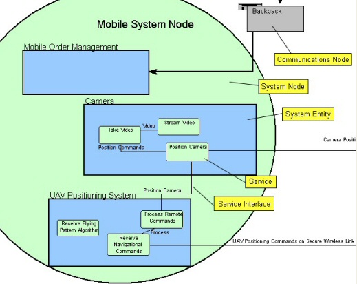
The following image shows an example of an SV-2 diagram containing a system node, Mobile System Node, which contains several system entities with services.