The Ward and Mellor state diagram is a more rigorous methodology than the standard state diagram. To ensure that state diagrams do not get confused with data flow diagrams, this methodology uses wide shallow rectangles with varying widths to allow for bypass transition arrows.
The life cycle of an engineering solution to a problem ranges from problem-dominated (finding the optimum solutions for the user requirements) to implementation-dominated (pushing the technical feasibility and limitations). Therefore, there must be a clear way to distinguish between the formulation of the problem and the technology that is chosen to implement the problem.
A real-time system is typically connected to sensors such as thermocouples, optical scanners, and contact probes, and can thus collect a continuous stream of unstructured data, analogous to the senses of living organisms. These inputs are used to continually change outputs, in a feedback system much like an “eye-hand coordination.” Such a system can also produce physical changes in the environment it exists in, such as temperature changes, valve positions, and so on.
Real-time systems usually require the simultaneous processing of multiple inputs to correlate values. The speed and precision demanded of real-time systems is faster and more critical than that of other systems.
A specification technique called a State Transition diagram is used to define the special type of process in a real-time DFD called a “control transform.” The state-transition diagram serves the same purpose as the structured English of a normal process specification, but it adds the graphic flexibility of being nonlinear and, therefore, is capable of defining an appropriate reaction to any number of possible conditions.
The State Transition diagram specifies the logic of the DFD by associating the incoming and outgoing flows as conditions with appropriate actions, and adding the knowledge (memory) of “what happened before.”
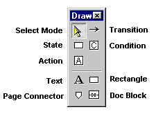
State Transition diagrams consist of states and transitions; the transition links the states. A transition consists of both a condition and an action. Every incoming event flow on the control bubble (transform) on the DFD must be associated with an appropriate condition on the corresponding state-transition diagram. Every outgoing control flow on the control bubble must correspond to an appropriate action on the state-transition diagram.
If the State Transition diagram is created as the child of a control transform on a Ward and Mellor data flow diagram (see Ward and Mellor data flow diagrams), the child diagram automatically contains the Action symbols and Condition symbols that are associated with the parent symbol.