Architecting and designing : Structured analysis and design : Methods and techniques for process modeling : Other diagrams for process modeling : Flow chart diagrams
  
Flow chart diagrams
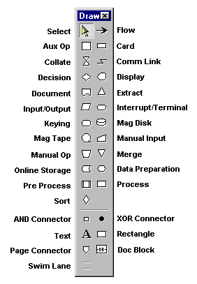
You can use flow charts to show program logic and system design. A software flow chart shows structured program logic; a system flow chart uses symbols that represent physical entities.
The Flow Chart methodology illustrates the flow of data depending on certain conditions.
Toolbar buttons
Select mode
Auxiliary operation
Collate
Decision symbol
Document symbol
Input/Output Symbol
Keying symbol
Mag tape symbol
Manual input
Online storage
PreProcess
Sort Symbol
AND connector
Text command
Page connector command
Swimlanes
Flow line
Card symbol
Comm link symbol
Display symbol
Extract symbol
Interrupt/terminal symbol
Mag disk symbol
Manual operation
Merge symbol
Data preparation
Process symbol
XOR connector
Rectangle command
Doc block symbol
See also
Other diagrams for process modeling