Create a physical data model from the logical data model you already created. Examine and add properties to your physical data model.
To create a physical data model from an ER diagram created in the previous lessons
1 In the Tutorial encyclopedia, under the Data Modeling tab of the Explorer, expand Models > Hotel Reservation System > Diagrams > Entity Relation. Double-click Hotel Check-In, or drag it onto diagram workspace.
2 Select Dictionary > Create Data Model > Physical Data Model > . The Create Physical Data Model Diagram dialog opens.
Diagram Name: Leave the default, which is the name of the ER diagram.
Super/Sub Resolution Method
In this dialog, you specify how you want to map super-sub relationships in the logical ER diagram to physical tables: the concept of super-sub relationships and the inheritance from the super to the sub does not exist in physical modeling.
The choices are:
▪Separate Tables: creates a separate physical table for every entity in a super-sub grouping. Attributes for each entity are mapped to columns in each respective table.
▪Merge Supertype to Subtype: creates tables for all sub-entities, does not create a table for the super-entity. Each table created for a sub-entity contains columns mapped from the attributes of the corresponding sub-entity, plus attributes 'handed down' from the super-entity.
▪Merge Subtype to Supertype: creates one table for the whole super-sub entity structure. Attributes from all super- and sub-entities are mapped to columns in the one table created.
▪Prompt for Each Super/Sub Group: System Architect will prompt you with a dialog enabling you to choose the mapping for each Super/Sub group as the transformation of logical to physical diagram takes place.
There are no super-sub groups in this data model, so you can leave the default at "Separate tables."
Resolve Non-specific relations: If any of the relationship lines between entities are non-specific, System Architect will convert them to constraints in the physical data model. Most DBMS do not accept non-specific constraints.
Name Mapping: You can choose how the case of names of Tables, Indexes, Constraints and Columns are mapped from the names of their corresponding Entities, Attributes, Relationships and Indexes. You can choose whether to replace non-standard characters, such as spaces, with underscores. Most DBMS do not accept non-standard characters.
Leave the default at Retain Case and toggle on "replace non-standard characters" for all four check-boxes.
3 Click OK.
System Architect will begin the mapping. A running log detailing the mapping will appear on the screen, under the title Generate Physical Data Model.
4 System Architect presents you with a dialog in which you must select the Model, DBMS and Database Name for the physical diagram. Leave Model at its default, Hotel Reservation System. Enter HOTEL in Database Name. From the DBMS list choose SQL Server 2005. Click OK.
Note The number of DBMSs listed depends on the DBMS's chosen in the System Architect Property Configuration dialog. The list of DBMS's can be changed at any time during a project by selecting Tools > Customize Method Support > Encyclopedia Configuration, selecting the DBMS you want from the Target Databases list, and reopening your encyclopedia.
5 The physical diagram is created, and the Generate Physical Data Model running log dialog completes. The last line of the log is "Physical diagram created."
6 Close the running log by clicking x in its top right corner.
Note If the physical diagram created is off to the right on the diagram workspace, and not visible on the screen, select View > Zoom > Used Area to view the entire physical diagram.
To move all the symbols, select Edit > Select All. Drag the group of objects where you want them.
7 Select File > Save Diagram to save the diagram.
Examine the physical table
The table in the physical model represents the table that will be implemented in the database. It contains specification of the table's columns, indexes, and physical properties such as Filegroup. Physical properties are DBMS-specific.
To examine a table in your physical diagram
1 Select the table Guest. Open its definition by double-clicking on it or by right‑clicking it, and then clicking Edit.
2 Notice in the Column grid of the table's definition dialog, that the columns have been mapped over from corresponding attributes in the corresponding entity of the logical data model.
Note Remember that column names default to the name of the underlying data element, and not to the name of the attribute.
3 The generic data types in the logical model have been mapped to SQL Server-specific types.
4 All data structures have now been expanded into relevant columns in the physical table.
In the logical model, you added the data structure Address to the logical entity for Guest. The data structure was composed of data elements Street, Town and District. Notice that Guest now has columns with those names.
5 A new primary key, number, has been migrated from the parent table Room as a foreign key. Both the PK and FK cells are checked for each column.
6 Column names have been derived from the data element name in the logical entity.
In the logical entity, the name of the logical data element was Guest Number (with an embedded space), and the attribute name was Guest#. The column is named Guest_Number.
Select Guest_Number: click in its name box, and then click Define at the bottom of the Column grid. You open the full definition dialog for this column.
Select the Source & Key Info. tab. In this tab, you can see the source attribute and data element for this column. It is read-only, but if you click Define you can view all the information on either source item.
7 Click OK or Cancel to close all dialogs.
Add physical properties unique to SQL server
The physical properties of a table vary depending on the target DBMS. For example, in SQL Server common properties include Filegroup and Filespec. Objects like triggers and stored procedures are common to almost all DBMS.
Before you can supply a Filegroup, you need to create the Filespecs:
1 In System Architect's Explorer highlight the Definitions branch and select New from the floating menu.
2 In the Select new type for all Methods dialog, scroll down and double click the SQL Server Filespec.
3 Enter System 12345 as the name of the SQL Filespec.
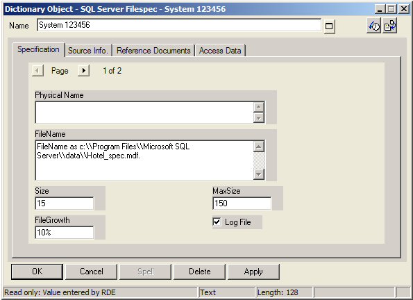
4 Enter the FileName as c:\Program Files\\Microsoft SQL Server\\data\\Hotel_spec.mdf.
Note The filename must be entered with double back-slashes.
5 Specify the Model name by selecting Choices and drag in the Hotel Reservations System.
6 Specify the Database Name by selecting Choices and drag in the Physical Database called HOTEL.
7 Click OK.
8 Enter the values as pictured below. If any values for properties are not entered, they default to the SQL Server default value.
9 Open the Guest table definition (right-click and select Edit or double-click it).
10 Click OK.
11 Using the same method as above create another SQL Sever Filespec named System123Log.
12 Enter the FileName as c:\\Program Files\\Microsoft SQL Server\\data\\Hotel_log.mdf.
Note The filename must be entered with double back-slashes.
13 Specify the Model name by selecting Choices and drag in the Hotel Reservations System.
14 Specify the Database Name by selecting Choices and drag in the Physical Database called HOTEL.
15 Click OK.
16 In the Filespec dialog enter the values as pictured below. Select the Log File, and then lick OK.
17 Open the Guest table definition (right-click and select Edit or double-click it).
18 Click the Triggers & Table Filegroup tab in the table Guest.
19 In the Filegroup box enter HotelSystem and click Define.
20 In SQL Server, filegroups are defined by filespecs.
21 In the FileSpec list box click Choices. The Select and Drag dialog gives you a list of the SQL Server Filespecs that you created previously.
22 Drag the System 123456 and System 123Log in the list box.
23 In the SQL Server Filegroup dialog box, click OK.