Create a sequence diagram of the interaction between a receptionist and a customer in a hotel business.
Like Use Case diagrams, you use Sequence diagrams to model scenarios in the system. They offer a different level of detail:
▪Use Cases (and the steps or textual descriptions that define them) offer a high-level analysis view of a system.
▪ Sequence diagrams offer a low-level analysis view of a system. This includes design information about the object interactions.
In a Sequence diagram, an object appears on the diagram as a vertical dashed line with the name of the object at the top and the name of the object's class optionally drawn below the object name. Events appear as horizontal lines between objects. Event lines are drawn in chronological order: from the top of the diagram to the bottom. They do not necessarily have a one-to-one correspondence with the steps defined for a Use Case scenario.
Keep the diagrams synchronized
To show the implementation details of a scenario, you can choose to draw either a Sequence or a Collaboration diagram, or both. System Architect automatically creates a Collaboration diagram from a Sequence diagram, and vice versa, when you invoke the Synchronize Diagram command from the Draw menu.
Finding objects by examining Use Case scenarios
The Use Case technique has become a popular vehicle for finding objects during an object-oriented analysis of a system. After modeling the scenarios for the way a system works or should work, you can then examine those scenarios to find the objects necessary for the scenarios to take place.
Examine Nouns and Verbs
One way to find objects is to examine the textual description or steps of every Use Case. Consider nouns in the textual description to be classes or class attributes and verbs to be methods of the classes.
For example, in the Make Reservation Use Case, in order for a Customer to request a reservation, two objects are necessary: Customer and Reception. In order for the step Check Diary for Room Availability to occur, the objects Room and Diary must exist. In order for the step Customer accepts accommodation to occur, the objects Customer and Room must exist, and so on. Looking at the steps of Make Reservation, you highlight possible objects in bold, possible class attributes in bold underline, and possible methods in italic.
1 Customer Queries for AvailableRooms
2 StoreCustomerDetails
3 CheckDiary for RoomAvailability
4 Room is Available
5 AdviseCustomer of Availability
6 Customer Requests Reservation
7 Provisionally Book Room
8 Figure Out Price, Advise Customer
9 CustomerAcceptsTerms
10 Provisionally BookRoom
11 CheckCustomerCredit
12 CustomerCredit Is OK
13 ReserveRoom
Build a Sequence diagram
Create a Sequence diagram, and make it a child of the Use Case diagram you created in the earlier section.
This will create a hypertext link between the two diagrams. For this tutorial, your Use Cases were in the Business Use Case View package. Build the Sequence diagrams in a Reservation System package in the Logical View package.
To build a sequence diagram
1 Open the Tutorial encyclopedia. (Select File > Open Encyclopedia > Existing. Select your Connection name, then highlight the Tutorial encyclopedia, click OK.)
2 In the UML tab of the Explorer, expand the Logical View package and right click Reservation System > New. The Select New Type for UML dialog opens.
3 In the Diagrams list, double-click Sequence to create a new Sequence diagram.
4 Type Make Reservation in the New Diagram dialog. Click OK on the Diagram - Sequence - Make Reservations dialog to keep the default settings.
Add objects to the sequence diagram
Add the other objects that you found in the steps of the Make Reservation Use Case: Reception, Reservation, Diary, and Room.
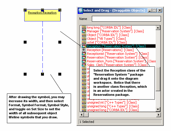
To add the object Reception, use a different technique than that used previously–reuse the class Reception of the package Reservation System that has been preloaded into this project encyclopedia.
1 Right-click the Sequence diagram workspace, and select Choices. You can view a list of classes and objects already established in this encyclopedia.
2 Select the Reception ["Reservation System"] [Class] and drag and drop it onto the diagram workspace. Note that there are two Reception classes–the Reception actor of the Reservations package that you created earlier, and a Reception class of the Reservations System package. Make sure that you drag this latter one onto the diagram workspace. An object Reception, instantiating the class Reception, is created. Close the Select and drag dialog.
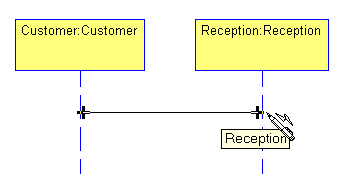
3 Position the object Reception so that it is parallel to the first object drawn, Customer.
Note By default, the Sequence diagram employs an invisible, horizontal grid that you draw and move symbols on. You can change the flexibility of this grid, or turn it off by selecting Format > Diagram Format > Grid > Reduced View. If you want to see the grid on the diagram workspace, select Format > Diagram Format > Display Options > Show grid.
4 Right-click the diagram workspace and select Choices. From the Select and drag dialog, drag and drop Diary ["Reservation System"] and Reservation ["Reservation System"] onto the diagram. Close the Select and drag dialog. Position the two objects in parallel to the other object lifelines.
Draw Message/Stimulus lines between objects
Message/Stimulus lines are drawn between objects to show how and when they communicate. These lines (which you can refer to simply as message lines) are drawn chronologically from the top of the Sequence diagram to the bottom.
The message line represents a message sent from one object to another, in which the 'from' object is requesting that an operation be performed by the 'to' object. The 'to' object performs the operation using a method that its class, or one if its superclasses, contains. Later in this tutorial, you can specify the method that a 'from' object is requesting the 'to' object to invoke. First, concentrate on the messages passed between the objects:
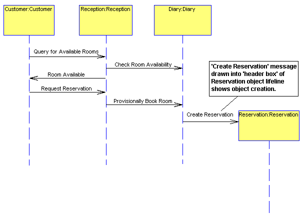
1 Select the Message/Stimulus tool from the toolbox and draw a message/stimulus line, starting at the object Customer and ending at the Reception object. When attaching the Event line to an object lifeline, make sure that you see a + mark on the intersection. This tells you that the lines are connected. Name the line Query for Available Rooms and press Enter. Reception responds to the event Query for Available Rooms by performing an action: It must check the Diary for room availability.
2 Draw a message line from the Reception object to the Diary object. Name it Check Room Availability. You will not model the return message from Diary back to Reception– leave it implied.
3 Draw a message line from the Reception object to the Customer object and name it Room Available.
The Customer can now request to reserve the room. Reception will book the room in the Diary, which causes the Reservation to be created.
4 Draw a message line between Customer and Reception named Request Reservation.
5 Draw an event line between Reception and Diary named ProvisionallyBook Room.
6 Increase the length of the first three object lifeline symbols (all but Reservation), by selecting the symbol and dragging its bottom handlebar downward.
Show object creation
The UML notation for showing that an object on a Sequence diagram is created is to draw a message line into the head of the name box at the top of the object lifeline. To show that Reservation is being created in this scenario, you will move the Reservation object lifeline downward so that you can draw a line into its header box.
1 Select the Reservation object and move it down on the diagram so that the next line drawn can be drawn into its 'header box'.
2 Draw a message line from Diary to the header box of Reservation and name it Create Reservation.
Complete the sequence diagram
The Reservation object compute its price and notify Reception, which will advise the Customer (Diary is not involved in this pricing process). If the Customer accepts the terms, Reception is notified, which reserves the room in the diary. Diary updates the Reservation status to Reserved.
To complete the sequence diagram
1 Draw a message line between Reservation and Reception and name it Indicate Total Price.
2 Draw a message line between Reception and Customer and name it Advise Customer.
3 Draw a message line between Customer and Reception and name it Accept Terms.
4 Draw a message line between Reception and Customer and name it Request Credit.
5 Draw a message line between Customer and Reception and name it Provide Credit Card.
6 Draw a message line between Reception and Diary and name it Reserve Room.
The Sequence diagram should now look like the following:
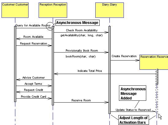
Add Activation Bars
A focus of control rectangle, or activation bar, is drawn on an object lifeline to show the period during which the object is performing an action. The activation bar represents both the duration of the action in time and the control relationship between the activation and its callers. The terms 'focus of control' and 'activation bar' are interchangeable.
To add activation bars
1 Select the Focus of Control tool on the toolbox, and drop one onto the Customer object lifeline. Notice that you can only drop a Focus of Control bar onto an object lifeline symbol. System Architect does not allow you to drop it onto empty diagram workspace.
2 Choose the Select Mode pointer from the toolbox (or press your Esc key) to get back your pointer. Select the Focus of Control bar, and drag on its bottom and top handlebars so that it covers the object lifeline at all points where it sends or receives a message.
3 Repeat steps 1 and 2 for the other object lifelines on the diagram. The diagram should look like the one pictured below.
Add a method to a message line
When one object sends a message to another object, it is in essence asking it to do something. The object receiving the message must be able to perform this task and return an answer to the sending object. The receiving class performs an operation - it uses a specific method to perform this operation. This method can be represented in a programming language such as Java or C++ or Visual Basic.
On the Sequence diagram, you can specify what method is 'invoked' by the sending of a message from one object to another. The method invoked belongs to the class that the receiving object instantiates. In System Architect you can specify what method is associated with each message in the definition of the line. This method should become part of the 'to' class definition, or the definition of a superclass of the 'to' class.
At an early stage of analysis, you would normally not spend too much time figuring out the methods invoked; this would be performed at a later stage of design, when you would return to this diagram. For time's sake, in this tutorial, you can add methods at this point.
Model the following: when Reception sends the message Check Room Availability to the object Diary, the method getAvailability is invoked. To reserve the accommodation, you need a start date, the duration of the stay, and the room type. These will be parameters of the method:
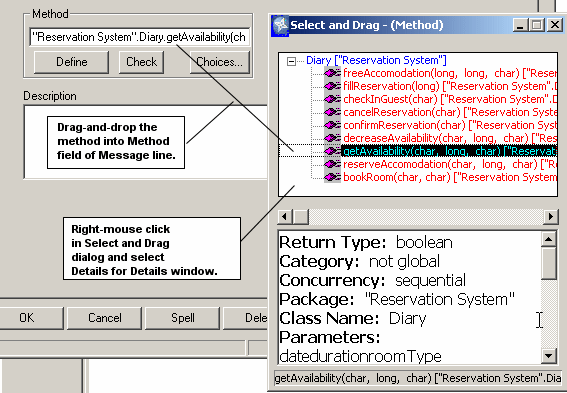
1 Open the definition of the message line Check Room Availability that is sent from the object Reception to the object Diary. (To open the definition, double-click the line or right click it and select Edit.)
2 In the definition dialog, select Choices for the Methods property. The Select and Drag dialog box opens, providing you with a list of all methods of the target class, Diary. Notice these are only methods for the class Diary (the System Architect notation is to put the method name (with parameters in parenthesis), a period, and the class name.
3 Drag getAvailability(Date, Duration, roomType).Diary into the Methods field. Close the Select and Drag dialog.
4 Once you drag the method into the Operations field, you can click Define to view the full method definition.
5 Click OK to close the Message line definition dialog. You notice that the name of the method has been added to the diagram, under the Message line.
6 Turn off the display of the method name–right-click the line and select Display Mode to open the Display Mode dialog. Toggle off Method and click OK.
Add a new method to a class
Next, add the method invoked by the message Provisionally Book Room that is sent from Reception to Diary.
First add this method to the Diary class:
1 Open the definition of the Diary object lifeline (right click and select Edit or double-click the symbol).
2 In the Definition tab of the definition dialog, click Define next to Class - (Class) Diary to open the definition of the class.
3 In the class Diary's definition dialog, click the Methods tab. You notice there are already a number of operations defined for Diary, but no method to book a room. You will add a new method.
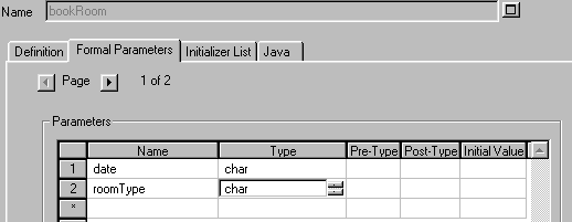
4 Scroll to the bottom of the Methods grid and type in bookRoom in the Name cell. Click Define.
5 In the method's definition, select the Formal Parameters tab. In the Parameters grid, type in date and press Enter. In the Type cell, press your 'c' key to select char.
6 Type in a second parameter, roomType, and specify the type as char. Click OK to close the method definition dialog, and OK again to close the class definition dialog.
7 Open the definition of the message line Provisionally Book Room that is sent from the object Reception to the object Diary.
8 Click Choices for the Methods property. The Select and Drag dialog box opens, providing you with a list of all methods of the target class, Diary.
9 Drag bookRoom(date, roomType)."Reservation System".Diary into the Methods box. Close the Select and Drag dialog and click OK.