Defining capabilities and capability relationships
You can use capability cluster diagrams to map out capabilities and show their dependencies to one another using a capability dependency line. You may also show decomposition of capabilities, developing a capability hierarchy, by drawing capabilities in their owning capability.
This diagram is provided to the DoDAF user as an optional diagram to work with. It is the same as the StV-4 diagram of MODAF, but since the DoDAF specification does not call for it, it does not have any prefix for the DoDAF user. It is simply called the capability cluster diagram.
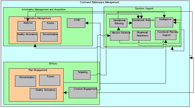
Pictured below is an example capability cluster diagrams. All rectangular symbols on the diagram, both big and small, represent capabilities. The lines drawn between capabilities are capability dependency lines. Some capabilities are shown drawn in other capabilities: this denotes composition of capabilities.
Automatically creating capability cluster diagrams from a capability taxonomy diagram
You can automatically create a capability cluster diagram from a capability taxonomy diagram.
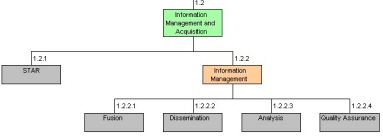
1 With the capability Taxonomy diagram open and in focus, save the most recent changes that you have made to the diagram by selecting File, Save Diagram.
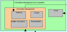
2 Select Tools, DoDAF Utilities, Convert StV-2 to StV-4. The capability Cluster diagram will be automatically created. capability symbols that are drawn beneath other capability symbols (denoting containment) will be drawn in their parent capability symbol on the capability Cluster diagram.
Result
=
Establishing relationships between capabilities
You use the capability dependency line to show how one capability is a supplier to another capability (the client).
1 Select the capability dependency line from the toolbar, and draw a capability dependency line from one capability to another.
2 Save the diagram.
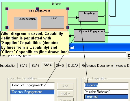
3 In the StV-4 tab of the capability definition, you will see a list of Supplier capabilities and Client capabilities, based on the dependency lines drawn on the diagram.
Result
Establishing hierarchies of capabilities in a capability cluster diagram
You can draw capabilities in other capabilities. In so doing, you establish a composition relationship between the capability that encompasses the capability enclosed in it. The nesting is captured in the capability definition, as Parent and Child capabilities, as soon as you save the diagram. If you have built a capability taxonomy diagram, you can automatically generate a capability cluster diagram.
1 Draw two capabilities on a capability cluster diagram.
2 Drag the handlebars of the capability you want to make the container, to make it larger.
3 Move the capability you want to have contained in the other capability, inside its enlarged symbol.
4 Save the diagram.
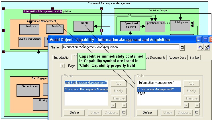
5 In the StV-2 tab of the capability definition, you will see a list of Parent capabilities and Child capabilities, which are filled in based on the containment of the symbols on the diagram.
Result
In the diagram pictured below, for example, the definition of the Dissemination capability shows that it is a child of (contained in) the capabilities Information Management and Plan Engagement.